
Venturer Models
VM32-D1000 "WESTERN" - 1/32nd Scale
Firstly, we'd like to sincerely thank you for your consideration and/or purchase of our flagship model, the brainchild of a genius designer, Sir Misha Black, and his principle cohort, John Beresford-Evans. When Black and the BR Design Research Unit developed the unique and iconic design of the D1000 BR CLass 52 Diesel Hydraulic locomotives, little could they have thought that their own dedicated work would create such a following of equally dedicated and genuine fanatics to the class. I am just one such fan.
The model is the culmination of several years of work and rework; from simple hand crafted modelling, to CAD profiling and high definituon laser sintered 3D printing. Throughout, my aim has been to produce a model which captures the true essence of the design, and provides an accurate representation in "miniature", albeit in "weighty" scales.
I hope you enjoy the ride as much as I have enjoyed the journey so far.......
Ian Allcroft
05/10/22

Before We Start
A word about working resin
The major body components are cast in a safe, non-toxic, durable resin which can be worked effectively with simple hand and machine tools, regular modellers glues, and a wide variety of paints. However, there are a few dos and don'ts........
DO Wash all the resin components in warm soapy water and dry thoroughly before working or painting.
Washing the parts will remove any remaining release agents used in the casting process to ease removal of the part from the mould. It is important to wash remaining traces away (including rinsing to remove traces on limonene from soap suds) to ensure glues and paints adhere correctly to the material.
DON'T wash using actetone or IPA (Isopropyl alcohol) as these will attack the surface of your resin parts.
Any questions : phone Ian on 07732 057585
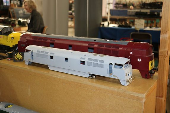
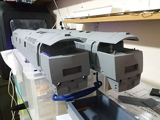
The first production kit here part-assembled for the G1MRA 75th Anniversary Show at Bicester 1&2 October 2022 with big sister Gauge 3 prototype behind.

Order of Construction
Recommended
1) WASH - Clean all resin parts with warm soapy water, rinse well (removing limonene residue) and allow to dry.
2) BODY - Joining the body sections
3) CHASSIS - Positioning the chassis fixing points
4) CABS - Joining Cabs to Body Sections
6) FILLING - Body filling and finishing
7) BATTERY BOXES - Battery box valances
8) CAB INTERIORS - Control desks, seats, etc.
9) FOSWORKS - radio/DCC/sound cradle mount
11) REAR BULKHEAD - Cab Rear bulkhead and Electrics
12) ETCHES - Windows, Fan cowls, Steps, etc.
Query? Ian 07732 057585
Parts List #1
RESIN
VM32-D1000-R1 - Cab incorporating roof cowls x2
VM32-D1000-R3 - Body Section - Cooler Groups x2
VM32-D1000-R4 - Body Section - Centre Boiler x1
VM32-D1000-R5 - Battery boxes x1
VM32-D1000-R6 - Headcode doors x2
VM32-D1000-R7 - Cab desk and floor x2
VM32-D1000-R8 - Cab rear bulkhead x2
VM32-D1000-R9 - Cab control desk x2
VM32-D1000-R11 - Refuelling theatre x1
VM32-D1000-R12 - Speedometer x1
VM32-D1000-R14 - Bogie Secondary Springing x4
VM32-D1000-R15 - Body mounting blocks x6
VM32-D1000-R16 - Cooler group fans x4
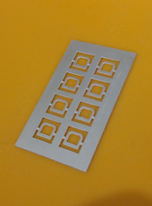
VM32-D1000-R17 - Battery box theatre plates x1 set
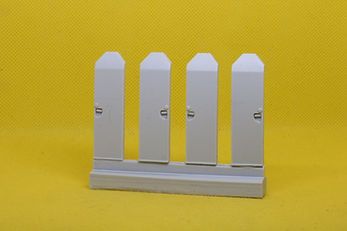
VM32-D1000-R18 - Doors x1 Set of 4
VM32-D1000-R19 - Body bracers (3D printed)
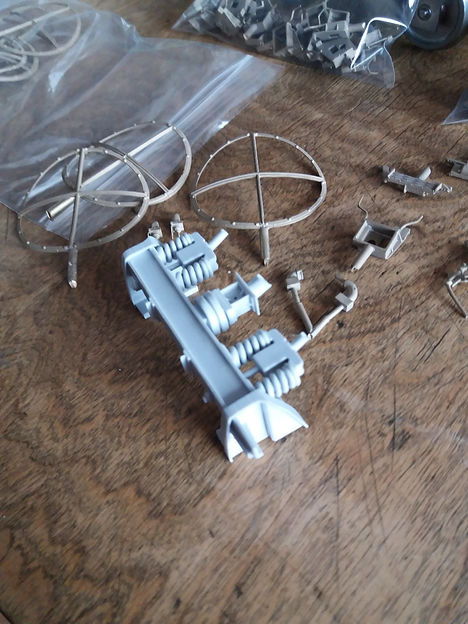
Single piece Secondary Springing - now how do we do that!!!
Click links to view each component part.
Parts List #2
BRASS
VM32-D1000-B1 - Windscreen wipers
VM32-D1000-B2 - Control desk handles
VM32-D1000-B3 - Sandbox cover plate handles
VM32-D1000-B4 - Buffers
VM32-D1000-B5 - Buffer stocks
VM32-D1000-B6 - Lamp brackets
VM32-D1000-B7 - Headboard mounts
VM32-D1000-B8 - Fire extinguisher handles
VM32-D1000-B9 - Couplings
VM32-D1000-B10 - Air brake pipes
VM32-D1000-B11 - Vacuum brake pipes
VM32-D1000-B12 - Pipes
VM32-D1000-B13 - Brake hanger shoes (Outers)
VM32-D1000-B14 - Brake hanger shoes (Inners)
VM32-D1000-B15 - Hand-brake wheel
VM32-D1000-B16 - Directional light covers
VM32-D1000-B17 - Steps
VM32-D1000-B18 - Drains
GLAZING
VM32-D1000-W1 - Windows - set

Parts List #3
ETCHES - Stainless Steel (SSE) and Nickel Silver (NSE)
VM32-D1000-SSE1 - Windows Main Framework
VM32-D1000-SSE2 - Front Window Frames
VM32-D1000-SSE3a - Side Window Frames - leading
VM32-D1000-SSE3b - Side Window Frames - trailing
VM32-D1000-SSE4 - Front Window Surrounds
VM32-D1000-SSE5 - Side Window Surrounds
VM32-D1000-SSE6 - Door kickplates
VM32-D1000-SSE7 - Fan Walkway Mesh
VM32-D1000-SSE8 - Fan walkway Frame
VM32-D1000-SSE9 - Bodyside access cover
(Note: Access port to compressor on B End - on one side only)
VM32-D1000-NSE1 - Roof Grills
VM32-D1000-NSE2a - Front valance foot-rest covers
VM32-D1000-NSE3b - Front valance foot-rest covers (additional separate etch)

BODY
Ensure all resin parts are clean and dry, having previously been washed in warm soapy water to remove any residues from the casting process.
General
I find working with cured resin to be very straightforward. It can be cut, machined, drilled, scraped, sanded and glued using typical modellers' tools, whilst being resilient and stable in use.
For the body construction I recommend using the following tools and materials:-
Scalpel, hand file, sanding sticks, Araldite 5 min epoxy (or similar two part epoxy glue), Superglue (both Hot and Rapid), Small clamps, Fine body-filler (Isopon P.38 car body filler is ok, fast setting, and of similar sanding properties to the resin when set; or epoxy putties such as Milliput or Sylmasta are fine, too).
If your kit includes body sections with the casting reservoir still attached, then a light hand-saw or tenon saw should be used to carefully saw this away.
![IMG_7665[1].JPG](https://static.wixstatic.com/media/0edb72_6a8ecb7b5d33412a8fd95158a1d97495~mv2.jpg/v1/crop/x_364,y_237,w_5229,h_3505/fill/w_258,h_173,al_c,q_80,usm_0.66_1.00_0.01,enc_avif,quality_auto/IMG_7665%5B1%5D_JPG.jpg)
VM32-D1000R3 (x2)

VM32-D1000R4 (x1)


Joining Body Sections
Parts:-
VM32-D1000R3 (x2), VM32-D1000R4 (x1), and VM32-D1000R19 (x2)
-
At one end of each body section (R3 and R4) there will be a rough edge where the reservoir was sited during casting. Clean these away by scraping (sharp scalpel edge) and/or sanding/filing, until smooth. Test fit the parts together. You are looking to acheive nice straight and flush butt joints. Inevitably with castings there may be small variations in fit, but the bodyside parts are sufficiently flexible to gently pull together. To hold the alignment along the length I stand the parts over the metal chassis with the body-sides either side of the chassis plate. With this done, look along the shoulders and roofline of the body sections to ensure they run true. It is most important that the shoulders are correctly aligned as errors in this will stand out in your finished model if not correctly fitted.
-
Using small clamps placed across the body joints, gently manoeuvre the parts to find the truest fit.
-
Once satisfied, epoxy one cooler group end (R3) to the centre section (R4), again checking alignment and gently clamp to hold. Allow to set.
-
Fit the internal body bracer R19 over the joint - epoxy in place and allow to set.
-
Repeat the joining procedure with the second cooler group section ensuring best alignment along the shoulders and roof line.
-
NOTE: The second batch of Western kits onwards come with a single body section VM32-D1000R30 (pictured left), this replacing parts R3 (2), R4 (1), and R19 (2).
Positioning the Chassis Fixing Points
-
Currently in draft. To be published shortly.

VM32-D1000R1 (x2)

VM32-D1000R3 (x1)
Joining Cabs to Body Section(s)
Parts:-
VM32-D1000R1 (x2) to Body
-
Currently in draft. To be published shortly.
Adding the Noses
-
Currently in draft. To be published shortly.
Body joint filling and finishing
-
Currently in draft. To be published shortly.
Battery Boxes and Valances
-
Currently in draft. To be published shortly.
Cab Interiors
-
Currently in draft. To be published shortly.
Fosworks Radio Cradle
(Optional)
-
Currently in draft. To be published shortly.
Fans
-
Currently in draft. To be published shortly.
Cab Rear Bulkhead and Electrics
-
Currently in draft. To be published shortly.

Etches
-
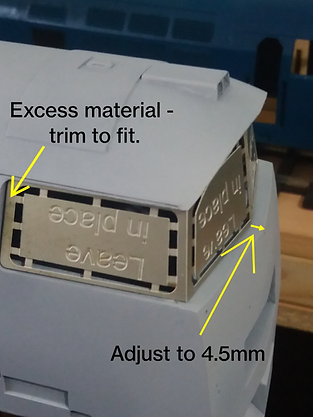
The main window frames are provided on the Stainless Steel Etch, part number VM32-D1000-SSE1 of which there are two. Carefully cut the outer tabs only to release the frame from the etch sheet, but leaving the areas marked "Leave In Place" as we'll remove thes after bending the findow frame into shape to fit the cabs.
-
The frame has three fold lines. The two corner folds forming the corner stanchions of the frames are inner fold lines, and the frame will be bent inwards along the line to give a clean outer fold to the frame. The centre-fold for the front windows, however, is an outer-fold, and will be bent with the half etch to the outer leaving the half etch fold line visible.
-

-
Test fit the framework in the cab and carefully adjust the folds until you have the correct fit, noting that there is a little excess material behind the trailing side windows which should be carefully trimmed/filed back until the front window fits correctly beneath the roof cowl and there is a 4.5mm ledge from window frame to the point of the nose.
-
When happy with the fit, carefully remove the remaining supporting etch marked "Leave in place" from the frame. Do not cement the frames into the cabs at this stage as it is much easier to fit the cabside windows into the frames before final fixing. I use a Demel tool with worn down cutting disc for removing the remaining supports in this delicate operation.
-
At this stage I suggest cleaning up the edges carefully with a fine file, and then prime the metal with an etch primer and then undercoat with colour to suit your model.
-
It is now advisable to fit the glazing into the front window recesses which helps with stabilising the frame, however this can be added later if you prefer. Laser-cut glazing is provided VM32-D1000-G1, and I use Canopy Glue to secure the pieces in place. [NOTE #1: Take great care if using any isocyanate glue as this will fog or damage the glazing if accidentally touched on the glazing faces, or used to excess. The use of isocyanate glues for any glazing fitting is NOT RECOMMENDED. NOTE #2: A video showing how I make up the Western Windows will available here shortly.].
-
Remove the Cabside Window Surrounds from the fret and, using canopy glue once again, secure the matching glazing into the surrounds. I find the best way to do this is to place surround face down on a clean flat surface and, using a small brush and a small drop of water washed into a small blob of canopy glue, carefully touch the brush to the edge of the etch, and allow capilliary action to draw the glue into the gap. Just do a few small areas first and allow to dry so that the glazing is held lightly in place, then repeat the process filling in the remaining areas until the whole of the glazing piece is secured in the frame.
Detailing
-
Currently in draft. To be published shortly.
-
Pre-heater roof cover plate - Hides the ON/OFF and recharging point.

Bogies
-
Currently in draft. To be published shortly.
Painting and Finishing
-
Currently in draft. To be published shortly.

Operating
-
Currently in draft. To be published shortly.